PlasmaCNC: Unterschied zwischen den Versionen
Zur Navigation springen
Zur Suche springen
Admin (Diskussion | Beiträge) (Die Seite wurde neu angelegt: „ == Ansprechpartner == Ska, Heiner == Beschreibung == PlasmaCNC == Call for parts == * Eisenprofile 50x50x3mm * Rail, *…“) |
Admin (Diskussion | Beiträge) Keine Bearbeitungszusammenfassung |
||
| Zeile 44: | Zeile 44: | ||
[[Kategorie:Projekt]] | [[Kategorie:Projekt]] | ||
Version vom 4. April 2017, 22:50 Uhr
Ansprechpartner
Beschreibung
PlasmaCNC
Call for parts
- Eisenprofile 50x50x3mm
- Rail,
- Monitor (DVI/HDMI?)
Hardware
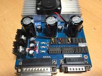
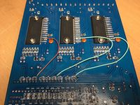
- Schrittmotor Steuerkarte tb6500 (modding durchgeführt/siehe Anleitung TB6560 Modding)
- Schrittmotor 3x
- Netzteil 24V/10A
- Arduino Gbrl Umwandler auf Parallelport
Software
- Mal sehen, aktuell ist GBRL eine option mit dem Universal GCode Sender
- Chillipeppr?
- Estlcam
Anleitung


TB6560 mod
ESSENTIAL MODIFICATIONS LIST:
- NEVER power up the unit without motors connected to the outputs and do not unplug a motor when the board is powered up. The poor grounding (note2) may destroy the 6560 chips. OK!
- Ground the heat sink for each TB6560 through its mounting screws. In the current design, there is a danger of blowing all chips if one goes bad. Adding the grounds helps protect them all. DONE!
- Disconnect the current reduction feature. This generates extra pulses and is not useful.DONE!
- Pin 7 on driver chip has a cap that sets the internal frequency. Replace the 1000pf capacitor which is installed with a smaller value capacitor (150 to 330 pF). DONE! 150pF verbaut.
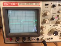
- Clean up the pulse to Clock (Step) and Direction signals. The pulse coming from the computer through the optocouplers is very slow on rise time (because of the optocouplers). The chip misinterprets the signals and misses steps. Bypass optocouplers.DONE!
- The way the ICs are getting power violates the manufacturers guidelines for power up and power down sequence. Do not use a single switch on the power line coming from the power supply. Either power the ICs on/off by a separate power supply or use a dedicated powerup/down circuit to deal with the sequence matter.TODO?
Links
- tb6560 modding mit Schaltplänen http://www.hobby-machinist.com/threads/retrofitting-the-famous-tb6560-cnc-board.34352/
- tb6560 modding mit Schmitt Trigger http://www.homediystuff.com/fixing-a-chinese-made-cnc-stepper-motor-driver-board-tb6560-chips/
- China-Steuerung mit TB6560 - ein paar Hintergründe - ein http://forum.zerspanungsbude.net/viewtopic.php?f=50&t=1937
- Fräsenbau mit tb6560 und Arduino Gbrl http://der-frickler.net/technik/frickelfraese
- Low-cost 4x4 plasma table, finished. http://www.cnczone.com/forums/plasma-edm-other-similar-machine-project-log/57192-low-cost-4x4-plasma-table-finished-13.html
- CNC PLASMA PROGRESS #1-#7 https://www.youtube.com/watch?v=qk5L0prby6I